

Introduction
When a plastic valve starts leaking, develops cracks, or refuses to move freely, the immediate symptom is only part of the problem. These failures can signal chemical incompatibility, thermal stress, pressure cycling, installation error, or gradual material degradation, each with different consequences for safety, uptime, and maintenance cost. This article outlines how to analyze the three most common failure modes in plastic valves, what evidence to examine, and how root-cause findings translate into better material selection, operating limits, and preventive action. The goal is to help readers move beyond replacing failed parts and toward fixing the conditions that caused the failure in the first place.
Why Plastic Valve Failure Analysis Matters
In industrial fluid handling, thermoplastic valves are prized for their exceptional corrosion resistance, lightweight construction, and cost-effectiveness compared to exotic metal alloys. However, when these components fail, the consequences ripple throughout the entire processing system. Plastic valve failure analysis is a rigorous engineering discipline dedicated to identifying the exact mechanisms and root causes behind premature degradation, fracture, or malfunction. By systematically dissecting failures, engineers can implement targeted corrective actions rather than relying on costly, repetitive component replacements.
The economic imperative for precise failure analysis is substantial. In continuous chemical processing, unplanned downtime can easily exceed $50,000 to $100,000 per hour. Furthermore, relying on guesswork to address a failed valve often leads to the installation of identical components under the same hostile conditions, guaranteeing a recurrence. A structured diagnostic approach transforms a catastrophic failure into actionable data, enabling plant operators to optimize system design, enhance safety protocols, and extend the mean time between failures (MTBF) by typical margins of 40% to 60%, aligning with reliability frameworks like ISO 14224.
Impact of leakage, cracking, and sticking
The operational manifestations of plastic valve failure generally fall into three categories: leakage, cracking, and sticking, each carrying distinct systemic impacts. Leakage compromises containment, leading to product loss, cross-contamination, and severe environmental or personnel hazards. A single leaking PVDF valve on an aggressive acid line can rapidly trigger EPA reporting thresholds if hazardous chemical releases exceed 100 pounds, while also violating fugitive emission standards such as ISO 15848-1 (which often limits permissible leak rates to 1×10^-4 mg/s).
Cracking presents a more immediate and catastrophic risk. Unlike ductile metals that may deform before breaching, rigid thermoplastics often fail in a brittle manner, resulting in sudden and total loss of fluid containment. Sticking, or stiction, disrupts automated processes by preventing precise flow modulation. When a valve sticks, pneumatic or electric actuators may stall by exceeding their typical 1.5x to 2.0x safety factor for torque, leading to batch inconsistencies, pump dead-heading, or the overloading of mechanical linkages.
Service conditions that increase failure risk
Thermoplastic materials are inherently sensitive to their operating environments, and specific service conditions drastically elevate the probability of failure. Temperature and pressure are inextricably linked in plastic piping systems; as operational temperatures rise, the pressure-handling capability of the polymer declines exponentially. Operating near these derated margins leaves zero tolerance for pressure surges.
To illustrate this sensitivity, the following table outlines typical thermal derating factors and expansion coefficients for common industrial plastics:
| Material | Max Operating Temp | Pressure Derating Factor at 140°F (60°C) | Coefficient of Linear Thermal Expansion (in/in/°F) |
|---|---|---|---|
| PVC | 140°F (60°C) | 0.22 (e.g., 150 psi drops to 33 psi) | 3.0 x 10^-5 |
| CPVC | 200°F (93°C) | 0.65 | 3.8 x 10^-5 |
| PVDF | 280°F (138°C) | 0.80 | 6.6 x 10^-5 |
Beyond temperature and pressure, the introduction of aggressive media or trace contaminants accelerates degradation. The presence of abrasive slurries erodes soft polymeric seats, while dynamic conditions such as rapid thermal cycling induce thermal fatigue. Expansion and contraction rates for plastics are typically five to ten times greater than those of metals, generating severe internal stresses if the piping system lacks adequate expansion loops or dynamic structural supports.
Common Plastic Valve Failure Modes
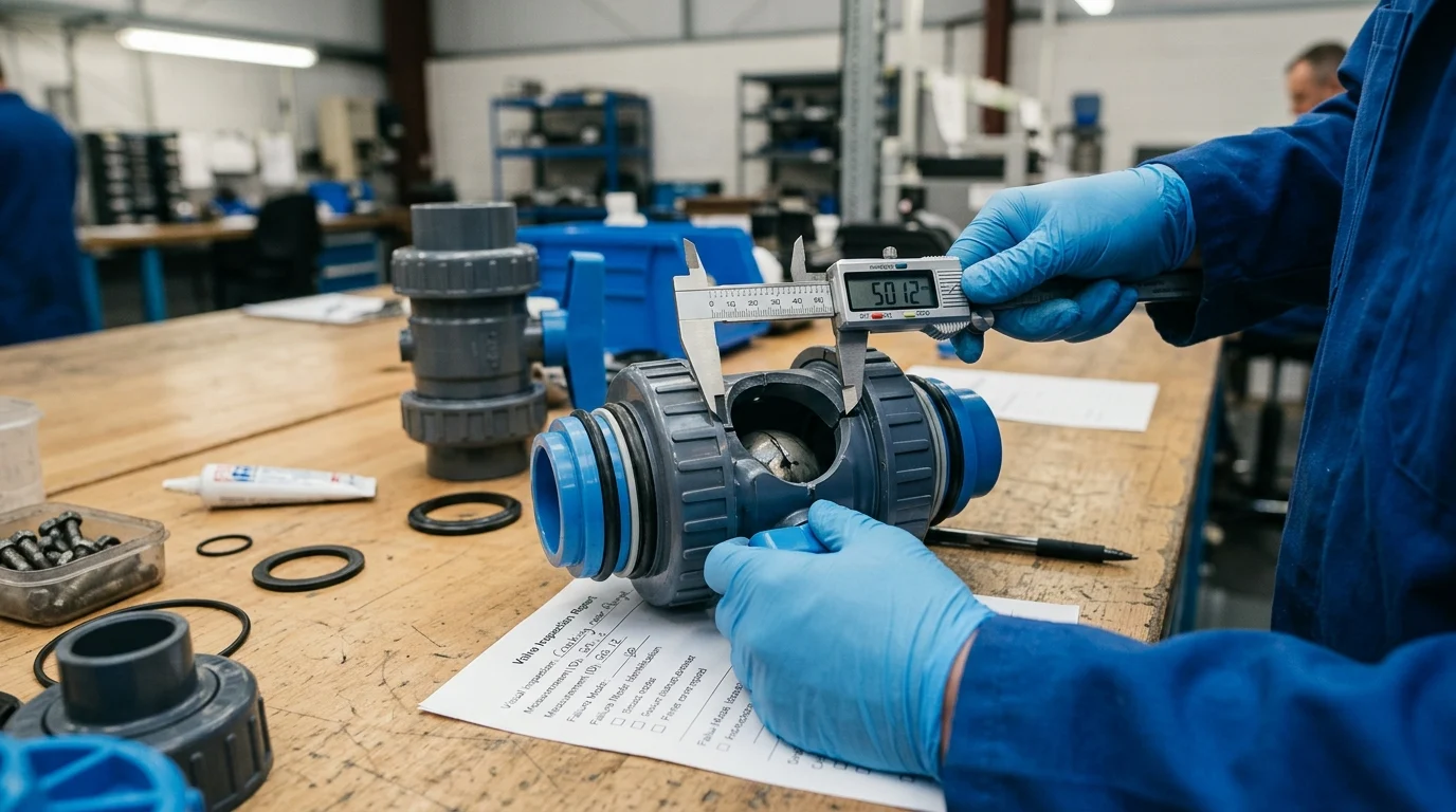
Classifying the physical mode of failure is the critical first step in the analytical process. Failure modes describe the observable physical phenomena—how the component broke or malfunctioned—rather than why it happened. In thermoplastic valves, these modes are broadly categorized into sealing failures, structural fractures, and mechanical binding. Accurately documenting the failure mode dictates the trajectory of the subsequent root cause investigation.
| Failure Mode | Typical Frequency | Typical Symptom | Common Affected Components |
|---|---|---|---|
| Leakage | 40% – 50% | Dripping, gradual pressure drop, crust formation | O-rings, PTFE seats, solvent-welded joints |
| Brittle Cracking | 20% – 30% | Sudden fracture, catastrophic fluid release | Valve body, actuator mounting pads, end connectors |
| Sticking | 15% – 25% | High operating torque, actuator stall, incomplete closure | Ball/stem interface, butterfly disc, elastomer seals |
Leakage at seats, seals, and joints
Leakage typically occurs at three primary interfaces: internal seats, dynamic seals (such as stem O-rings), and static external joints. Internal seat leakage often results from the cold flow (creep) of PTFE seats under continuous mechanical loading, particularly when differential pressures exceed 1,000 psi in high-performance plastic valves. Once the seat deforms permanently, it can no longer maintain a positive shut-off against the ball or gate.
Dynamic seal leakage frequently stems from compression set, where an elastomer O-ring loses its elastic memory due to thermal aging or chemical attack, flattening out and creating a leak path. Failure is often imminent when an elastomer exceeds a 25% to 30% compression set per ASTM D395 testing. Joint leakage at the valve ends is usually associated with compromised solvent cement welds, threaded connection yielding, or improper flange gasket compression, allowing media to bypass the intended containment boundaries.
Brittle cracking, stress cracking, and fatigue
Structural failures in plastic valves are dominated by Environmental Stress Cracking (ESC), which accounts for approximately 25% to 30% of all plastic component failures in industrial service. ESC occurs when a polymer is subjected to a combination of tensile stress and a mild chemical agent that does not degrade the plastic outright but significantly lowers its fracture toughness. This results in brittle crack propagation without macroscopic yielding.
Fatigue cracking is another prevalent mode, driven by cyclic loading such as repetitive valve actuation or vibration from nearby pumps, often causing premature failure before reaching the standard 100,000 to 250,000 cycle design life. In fluid systems, water hammer—a hydraulic shockwave capable of generating transient pressure spikes up to three times the normal operating pressure—can initiate microscopic crazing. Over time, these crazes coalesce into macro-cracks, culminating in sudden brittle fracture, often at stress concentrators like sharp internal corners or molded threads.
Sticking from friction, swelling, or deformation
Mechanical sticking, or stiction, primarily affects rotary valves such as ball and butterfly designs. A leading driver of this failure mode is elastomer swelling. When seal materials absorb incompatible fluid components—for instance, an EPDM O-ring exposed to trace hydrocarbon solvents—the elastomer can swell by more than 20% in volume. This expansion extrudes the seal into the valve's dynamic clearances, drastically increasing breakaway torque by 300% to 500%.
Deformation of the valve body or internal components also causes sticking. If a plastic valve is subjected to piping loads (bending moments) due to inadequate pipe supports, the internal cavity may distort, pinching the ball or disc. Additionally, severe thermal gradients can cause differential expansion between the internal components and the outer body, leading to temporary or permanent binding that overwhelms the actuator's torque output.
Root Causes of Plastic Valve Failure
While the failure mode identifies how a valve failed, the root cause explains why. Root causes are the fundamental design flaws, material incompatibilities, or operational deviations that initiated the failure mechanism. In complex fluid handling systems, failure is rarely the result of a single isolated event; rather, it is typically the culmination of interacting vulnerabilities. Identifying the exact root cause is essential for breaking the cycle of recurring failures.
Engineering analysis generally traces plastic valve failures back to three distinct categories: application mismatches, manufacturing defects, and procedural errors during installation or operation. Addressing these requires a holistic review of the system's process parameters, procurement specifications, and maintenance logs.
Material, media, temperature, and pressure mismatch
The most frequent root cause of plastic valve failure is a fundamental mismatch between the chosen materials and the actual service conditions. Chemical incompatibility is a primary offender; for example, utilizing unplasticized PVC with concentrated sulfuric acid (concentrations exceeding 90%) will lead to rapid oxidative degradation, a mismatch easily avoidable by consulting ASTM D543 chemical resistance standards. Similarly, trace chemicals not listed on the primary process flow diagram, such as cleaning agents or lubricants, can initiate localized chemical attacks.
Temperature and pressure mismatches often occur when engineers specify valves based on ambient baseline ratings without applying the necessary thermal derating factors. If a process experiences temporary temperature excursions—such as a CIP (Clean-In-Place) cycle reaching 180°F (82°C)—a valve specified for a baseline of 120°F (49°C) will suffer immediate mechanical yielding or severe seal degradation, even if the excursion lasts only a few minutes.
Manufacturing and assembly defects
Even when properly specified, a valve may fail due to defects introduced during the injection molding or assembly processes, accounting for roughly 10% to 15% of premature failures. Molding defects such as voids, sink marks, or pronounced weld lines (knit lines) act as internal stress concentrators. If a molded PVDF valve body retains residual molded-in stresses exceeding 5 MPa, it becomes highly susceptible to premature stress cracking when exposed to normal operational loads.
Assembly defects at the factory level also compromise longevity. Pinching or rolling of O-rings during the insertion of the valve stem can create immediate micro-leaks or localized wear points. Furthermore, inconsistent application of lubricants on dynamic seals during assembly can lead to dry-running friction, accelerating wear and causing early-stage stiction before the valve has even reached a fraction of its rated cycle life.
Installation and operating errors
Human error during installation and operation remains a leading root cause of thermoplastic valve mortality, representing up to 40% of field failures. Over-tightening of threaded connections is notoriously common; applying excessive torque (e.g., exceeding 25 ft-lbs on a 1-inch NPT plastic thread) induces massive hoop stresses, virtually guaranteeing a split in the female valve port. Furthermore, forcing misalignment corrections by bolting up misaligned flanges places permanent bending moments on the valve body.
Operationally, improper actuation speeds induce catastrophic hydraulic shocks. If a pneumatic actuator is configured to close a 4-inch ball valve in under 0.5 seconds on a high-velocity liquid line (e.g., >5 ft/s), the resulting water hammer can shatter the valve internals or rupture the adjacent piping. Operating valves in a throttled position when they are designed strictly for on/off service (such as standard block ball valves) also causes rapid cavitation and localized erosion of the seating surfaces.
How to Perform Plastic Valve Failure Analysis
Executing a successful plastic valve failure analysis requires a disciplined, evidence-based methodology. Jumping to conclusions based on visual symptoms often results in treating secondary damage rather than the actual root cause. Industrial failure analysis typically follows a structured framework, such as the 8D (Eight Disciplines) problem-solving methodology, modified specifically for polymer engineering. A comprehensive third-party analysis typically requires 2 to 4 weeks and $5,000 to $15,000 in laboratory costs, a fraction of the cost of continued unplanned downtime.
The analytical process moves sequentially from non-destructive macro-observations to destructive micro-analysis. By preserving the physical evidence and correlating it with historical process data, engineers can reconstruct the sequence of events that culminated in the valve's failure.
Step-by-step analysis workflow
The workflow begins with comprehensive data collection before the failed component is even dismantled. Engineers must gather the Piping and Instrumentation Diagrams (P&ID), material specifications, maintenance logs, and typically 30 to 90 days of SCADA data capturing pressure and temperature trends at the time of failure. Following data acquisition, a meticulous visual examination is conducted, documenting the valve's orientation, flow direction, and external damage using high-resolution photography.
Once the external context is established, the valve is carefully disassembled. This step requires precision to avoid introducing new damage that could be mistaken for operational wear. Each internal component—seats, seals, stem, and ball/gate—is isolated and inspected. Finally, the workflow transitions to laboratory testing, where material properties are verified against virgin resin baselines to determine if chemical degradation or thermal aging occurred during service.
Inspection and testing methods
Advanced inspection and testing methods are critical for diagnosing polymer failures.
Corrective Actions to Prevent Repeat Failures
Key Takeaways
- The most important conclusions and rationale for Plastic Valve
- Specs, compliance, and risk checks worth validating before you commit
- Practical next steps and caveats readers can apply immediately
Frequently Asked Questions
What is the first step in plastic valve failure analysis?
Classify the failure mode first: leakage, cracking, or sticking. Then document the exact location, service media, temperature, pressure, and cycle history before replacing the valve.
Why do plastic valves leak at seats or joints?
Common causes include worn O-rings, damaged PTFE seats, poor solvent-welded joints, and chemical attack. Check seal compatibility, assembly torque, and whether pressure or temperature exceeded derated limits.
What usually causes cracking in a plastic valve body?
Cracking often comes from overpressure, thermal cycling, impact, or incompatible chemicals. Review temperature derating, surge events, and piping support to reduce stress on the valve body and end connections.
Why does a plastic valve start sticking during operation?
Sticking is commonly caused by buildup, abrasive wear, swelling elastomers, or misalignment. Inspect the ball or disc, stem interface, and seals, and confirm the actuator torque matches actual operating conditions.
How can I prevent repeat plastic valve failures?
Match the valve material to the media, respect temperature-pressure derating, support thermal expansion, and inspect seals regularly. A root-cause review is more effective than replacing the same valve in the same service.


